
Mad about Science: Diesel-electric locomotives
By Brenden Bobby
Reader Contributor
If you grew up around here, you likely learned a bit about steam locomotives during Pacific Northwest History class in high school. Since at least the 1890s, the bulk of this area’s population has relied on the railroads, which moved lumber from the region and shipped it elsewhere for big profit.
Steam locomotives worked by housing a large boiler tank over a coal-stoked fire. Steam pipes were vented to various mechanical devices on the engine of the locomotive, which would drive pistons designed to turn the wheels. The use of steam locomotives advanced with technology, which also included functions such as providing heating for passenger cars.
That was a massive oversimplification of the functioning of steam locomotion, but it sets a baseline.
Steam locomotives are rarer now, with heavy freight haulers having been replaced by diesel-electric locomotives, which begs the question: Why diesel-electric and not simply diesel?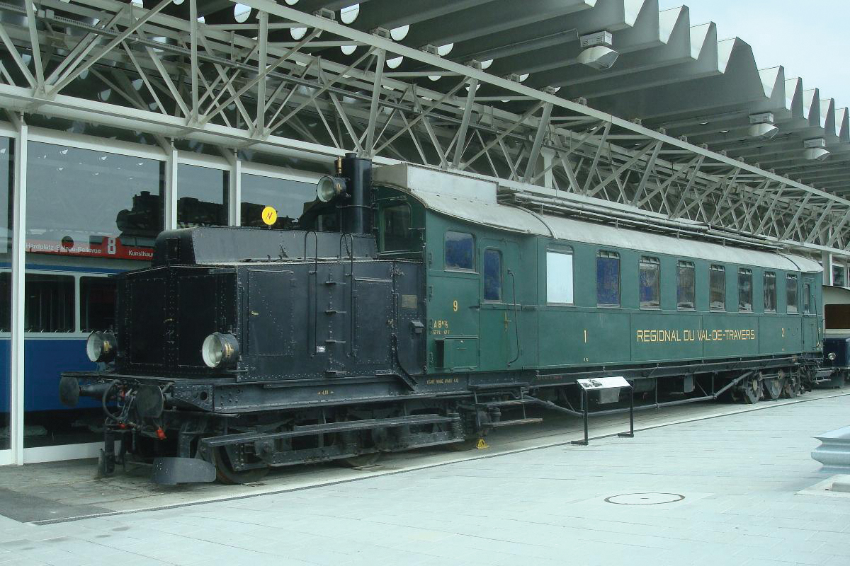
Let’s compare the efficiency of a diesel-electric locomotive with a diesel long-haul truck.
A diesel-electric engine in a locomotive is designed to achieve maximum efficiency under predictable and controlled conditions.
Converting diesel fuel into electrical energy for use in a locomotive’s drivetrain is up to four times more efficient than when being used by a long-haul truck. On average, a locomotive of this design can transport 2,000 pounds of freight up to 500 miles on a single gallon of fuel. In that case, why even bother using a diesel truck?
Both vehicles have their place in the distribution chain. Freight trains are designed to carry huge quantities of goods across vast distances with minimal stops. This means that it would be extremely inefficient to have a train station built into your department store to stop and unload at every town, as the train would need to devote more time and energy to stopping and starting repeatedly. Instead, trains transport goods to distribution centers that can transfer smaller loads to fleets of larger trucks that can navigate highways and town roads to deliver individual goods to store shelves and post offices.
Most freight locomotives are built similarly for ease of use, repair and to follow specific regulations related to railway operation — unlike passenger vehicles, which are more customizable and vary from maker to maker. Uniformity is the name of the game when you’re seeking prime optimization for distribution.
There are walkways on either side of the locomotive, with paneling that allows for engineer access to the internal components. The operator’s cab is small and located where you’d expect, with the windowed section near the head of the train above and behind the cowcatcher and the nose of the vehicle. There is a door on the nose of the vehicle that allows for access, with a small bathroom below the seating area — though, to be honest, calling it a “room” is a bit of a stretch, as there’s just enough room to sit and take care of business.
The auxiliary cab is located directly behind the operator’s cab, which contains several vital electronics for maintaining the locomotive’s operation, with the engine located behind that.
The engine runs similarly to virtually any other diesel engine, with diesel fuel powering pistons that crank a huge alternator that acts as an electrical generator powering the locomotive. This is primarily how the engine differs from an automobile, which utilizes internal combustion engines as a means of locomotion. Large traction motors are what drive the locomotive, and these are powered electrically and not directly by the diesel engine.
Those means of locomotion utilize DC current, which is converted from AC current through components in the aux cab. This is one of the more technical and complex aspects of the locomotive, so if you are looking for more information about this process, you may want to ask an engineer or check out a book from the library about locomotives or electrical systems.
As you can imagine, anything involving movement and a large amount of electrical power will create a lot of heat. There are vents above the trucks — where the wheels are housed — that pull in air and vent it directly to the traction motors to keep them cool during operation.
On the topic of heat, braking a vehicle of this size and weight is an impressive feat. There are two forms of braking involved, called dynamic braking and pneumatic braking. The pneumatic braking system essentially uses huge air compressors to drive a piston that controls a brake shoe, creating friction that slows the train by converting energy into heat. There is a brake pipe that is connected to the trailing cars that allows for this to function on the linked cars as well. Each car has its own air reservoir, which can be seen as an air tank near the head of the freight car above the wheels.
Dynamic braking involves using magnetic fields surrounding the traction motors to oppose their spin and slow the vehicle down. The traction motor is essentially two components with the internal rotor and the exterior stator. The stator surrounds the rotor like a Pringles can around a stack of chips. When electrical energy is applied, it creates magnetic fields that then make the rotor spin. An engineer can change the direction of the field to encourage the rotor to spin in the opposite direction, effectively using magnetic fields to slow the vehicle rather than creating friction through metal contacts directly to the wheels.
This is just a brief glimpse into the complex workings of one of our most efficient vehicles.
Stay curious, 7B.


 Coming up this week! Don’t miss Live Music, the Summer Sampler, the Art Party, Monarch Grind, the Sandpoint Renaissance Faire, and more! See the full list of events in the